Circuit Diagram Voltmeter Potentiometer Slide Potentiometer
Potentiometer diagram, symbol, and construction Circuit diagram voltmeter and ammeter Digital voltmeter circuit diagram using icl7107 / 7106 with pcb
10k potentiometer circuit diagram - Wiring Diagram and Schematics
Basic principles of potentiometers/variable resistors The potentiometer and wiring guide Slide potentiometer wiring
Potentiometer schematic
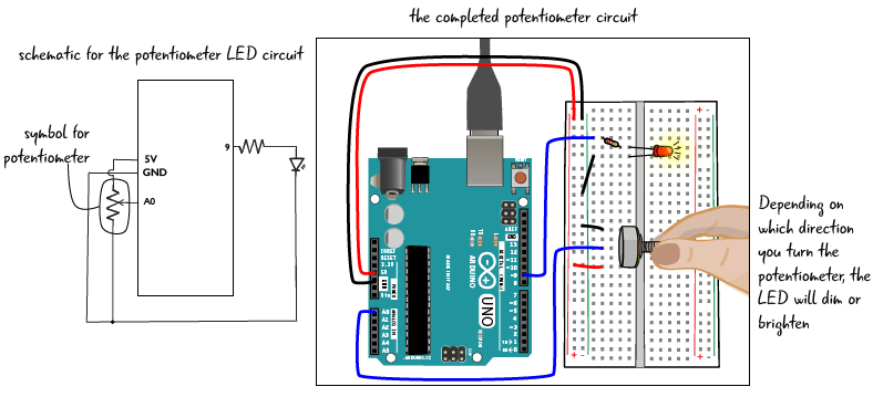
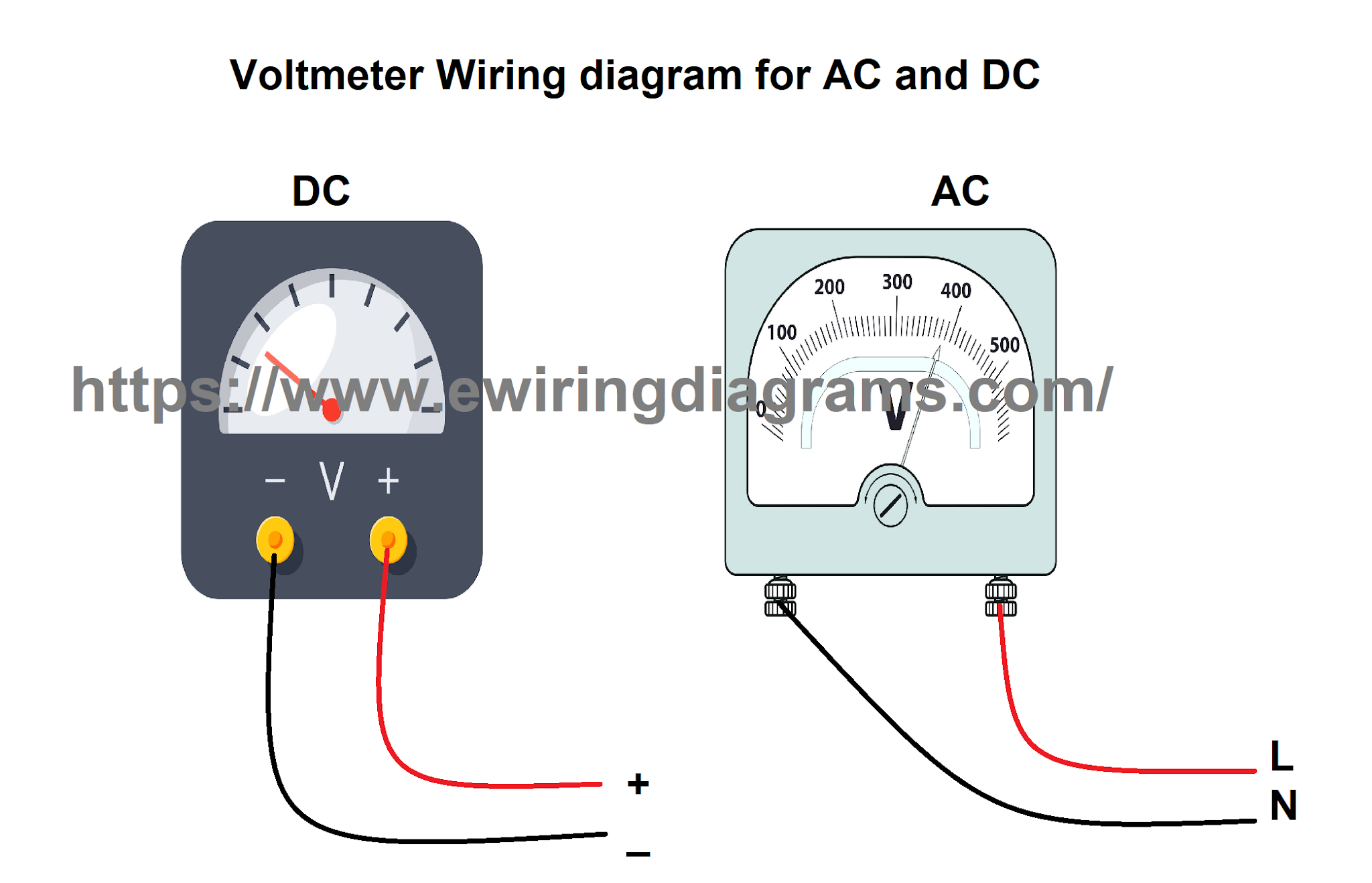
10k potentiometer circuit diagramHow to wire voltmeters for 3 phase voltage measuring Digital circuit voltmeter icl7107 using simple diagram meter dc pcb completely voltage negative figurePotentiometer circuit diagram resistor led circuits wiring simple control dim electronics electronic variable brightness resistance turn change guide build.
L4: potentiometersCircuit diagram voltmeter Potentiometers potentiometer arduino 10kω18+ potentiometer pinout diagram.

Potentiometer resistor potensio wiring variable potensiometer potentiometers tegangan menurunkan parallel wire symbols
Variable resistor pin configurationPotentiometer circuit pot diagram working construction method rheostat definition [proper] potentiometer connection and circuit diagramVoltmeter parallel connected voltage circuitglobe.
Potentiometer constructionalVoltage calculate potentiometer range circuit divider resistance load schematic change variable output would parallel questions significance explain effect loading source Potentiometer schematic potentiometers variable resistors figure principles basic r4 components passive doeeet connectionWhat is voltmeter?.

Potentiometer circuit diagram
Principles potentiometers potentiometer basic diagram wiring components linearWiring phase voltage electrical diagram wire measuring voltmeters voltmeter circuit panel meter projects three analog digital board diagrams tutorials make Solved: calculate how the output voltage range would chang...Potentiometer circuit.
Potentiometer circuit diagramPotentiometer circuit diagram connection voltage divider control board simple light led choose electrical pcb What is potentiometer (pot)?Potentiometer circuit resistor led circuits wiring brightness variable dim resistance turn.

Potentiometer connection
3 digit digital voltmeter circuit diagramThe potentiometer and wiring guide .
.
![[Proper] Potentiometer Connection and Circuit Diagram - ETechnoG](https://3.bp.blogspot.com/-7pcmbMVljr8/XNV3lTwW0NI/AAAAAAAAB2A/3j9EWjEKIhkM-EN5eRJvIN2s6xnrr3bvACLcBGAs/s1600/Potentiometer%2Bterminals.png)

18+ Potentiometer Pinout Diagram - MylesCartner

Potentiometer Circuit Diagram | EdrawMax Template

Digital voltmeter circuit diagram using ICL7107 / 7106 with PCB

Variable Resistor Pin Configuration
Potentiometer Schematic
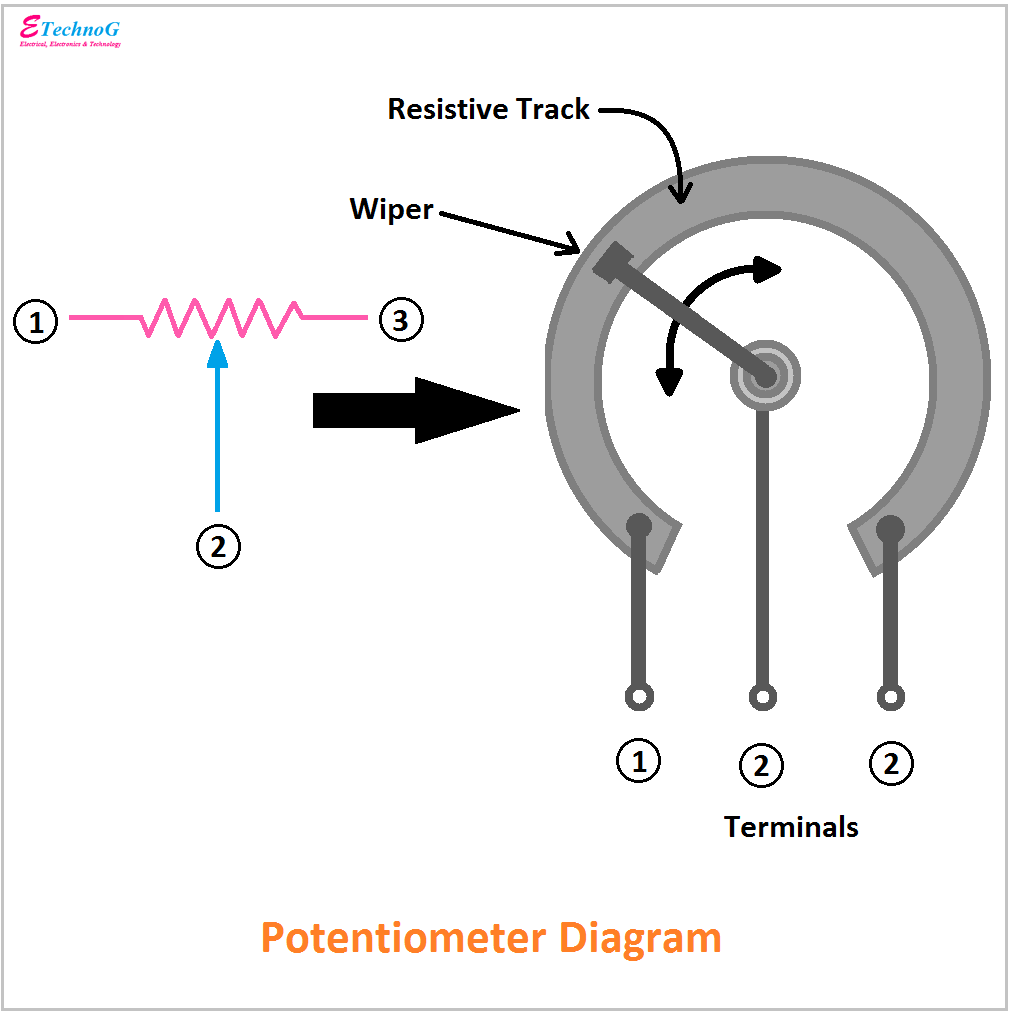
Potentiometer Diagram, Symbol, and Construction - ETechnoG

Solved: Calculate How The Output Voltage Range Would Chang... | Chegg.com
Circuit Diagram Voltmeter And Ammeter